Ready to be Hafted

162591479

Spent the last few days polishing this bearded axe.  It’s now ready to be hafted.  I call this finish “file satin.”  Basically, I forge the axe as closely as I can to the shape I want.  I leave a little extra meat for the grinder.  I then give it a very course grinding to remove scale and pits.  I then draw file to the final shape I want.  This is followed by hand polishing with wet/dry paper then emery compound.  Finally, I use oil on a scotch-brite pad and satin the whole thing.  This gives a very well defined shape, but upon closer inspection small forge pits and file marks are evident to add historic character.

162591478

I do some final shaping of the socket to ensure a nice fit with the haft, and then put a small chamfer on the edges.  While most of the examples I’ve seen are too corroded to support the idea of this small chamfer, I do it because it adds a little depth to the axe head, and protects the user from cutting his or her fingers on the hard edges.  Considering the amount of file work you see on many historic weapons, I think it is historically plausible.

162591481

The edge is hand polished to sharpness with stones.  I am looking for a slight apple seed bevel, but because of the wedge shaped design of this axe, the apple seed bevel is very small because the wedge shape of the axe will naturally support an aggressive cutting edge without too much meat behind the edge.  This design allows for an extremely sharp edge that is well supported.  This axe could do some real damage to an opponent’s shield or person.  I do the final sharpening with a high grit diamond hone followed by a leather strop which makes a hair shaving edge.

162591480

Specs:

  • Socket and Body: 1018
  • Edge bit: 1080
  • Blade width: 4.75″ (12,1 cm)
  • Overall length (from pole to top tip of blade): 6.375″ (16,2 cm)
  • Weight: 1.25 pounds (567 grams)

I’ll post final pictures after it has been hafted.

WIP Bearded Axe

bearded axe husbyborg

I’m getting ready to polish a small bearded axe that is inspired by an axe that I documented with Swordsmith Peter Johnsson in Uppsala, Sweden.

We were drawn to this axe because of it’s elegant lines, and stout shape.  While it’s profile makes it look like a thin axe, when viewed from the top, it is clear that this axe is all business.  The body is nearly wedge shaped.

bearded axe husbyborg top

The body and socket are 1018 and the bit is 1080.  Blade width is 4.75″ (12,1 cm) from tip-to-tip.  It is 6.25″ (15,9 cm) long.

A Visit with Dr. K. Robert Cashen

Swedish Swordsmith Peter Johnsson and I were able to visit Kevin Cashen and his lovely wife Karen at their home in Michigan.  Kevin, whom I have dubbed “Dr. K. Robert Cashen,” because of his important work on metallurgy for bladesmiths, opened his lab to us and showed us numerous examples of his research.

medium
Peter Johnsson and Kevin Cashen discussing retained austenite with the scanning electron microscope in the background.

I believe his work is critical for bladesmiths because Kevin, as a maker, is keenly aware of the difficulties that bladesmiths run into trying to produce a quality blade with a sound heat-treat.  Kevin has a variety of microscopes (even a scanning electron microscope) which clearly shows the different steel structures.

medium1
Kevin polishing a sample to be photographed under the microscope.

Kevin’s research allows bladesmiths to combine practical techniques with sound science to achieve a quality heat-treat.  This is very valuable because it show definitely what structures we are obtaining when we heat-treat our blades.  It further allows us to make adjustments to obtain an optimal blade.

medium2
There is an intense discussion taking place right behind me.

I really want to thank them for opening their home to us.  They are the kindest people, and we’ve become good friends.  It is refreshing to meet people who are free of duplicity and are genuinely interested in fellowshipping with other makers.

Of course after all the intense metallurgical discussion, we retired to Kevin’s newly remodeled “man-cave” to drink some BEER!

medium3
Beer in the man-cave!


Neckbiter (Petersen Type G/H) Axe

large

The blade is 4.5″ (11,4 cm) wide. Overall length is 7.5″ (19,5 cm). Socket and body are 1018 low carbon steel and the bit is 1080 high carbon steel.  Blade is tempered to 50-55 Rockwell.  The haft is 30.5″ long and is made of burnt hickory.

SOLD

If you are interested, contact me at ericmycue374@comcast.net

large3

large2

Introducing Neckbiter

Finished polishing and hafting the Type G/H.  I want to name this axe Neckbiter.  Not sure how you would say that in Old Norse.  Anyway, that is the feeling of this light and agile axe when you swing it.  I see a warrior with a shield in one hand and Neckbiter in the other finding a hole in an opponent’s guard and then plunging it into his neck.  I apologize for the poor pictures.  I am in the process of acquiring better photo equipment.

large

In many ways, this axe was a leap forward for me.  I was able to use more authentic techniques and tools to create this axe.  Being able to forge-weld eye socket, body, and bit together, and have it turn out virtually invisible, has been a goal of mine for years.  This opens the door to many new options for making Viking axes.  I have quite a few projects planned for the near future using these new methods.

Back to Neckbiter: The blade is 4.5″ (11,4 cm) wide. Overall length is 7.5″ (19,5 cm). Socket and body are 1018 low carbon steel and the bit is 1080 high carbon steel.  I used my Rockwell files to test the edge post-heat treat and it comes out between 50 and 55 Rockwell.

large1

I purposely left some of the files marks in the finish.  These files marks are often seen on period originals; and I have to admit, I was not brave enough in years past to leave them on a piece.  Now a days, I decided I’m going to make something that pleases and inspires me.  Hopefully, others will find it inspiring too.  Interestingly enough, it is actually harder to do this finished than just putting a high grit belt on the grinder and removing all the marks.  I also left some of the forge pits in the piece.  After all, this axe was forged to shape.  So once I filed it to the dimension I wanted, I stopped.  If there was a pit, well the pit stayed.  I hand polished the body to a high grit then drew it back with a scotch-brite pad.  The edge was buffed to a near mirror finish to create a pleasing contrast.  The edge is hair shaving shape.

When I do a haft, I fit it through the bottom of the socket.  I know that some makers make a haft that is wider at the top and slip it through the top of the axe head and slide the head up till it wedges at the top of the haft.  I’m not saying this is wrong.  No one knows for sure how the Viking smiths did it, but there is evidence that the axe was driven onto the haft then wedged at the top.  I personally documented multiple axe heads with Peter Johnsson in Sweden that had the iron wedge with the axe head.  Here is a picture of one such wedge:

medium

I find that using a wooden wedge to spread the haft sideways in the socket and a metal wedge to spread it the opposite direction, creates a wider section at the top of the head that makes it nearly impossible for the axe to come off the haft.  On Neckbiter, I inserted a wooden wedge and made an iron wedge similar to the one I documented in Sweden to secure the head on the haft.

large2

The haft is 30.5″ long.  It is made of burnt hickory which has been sanded and polished to a smooth finish.  It has been treated with linseed oil to preserve it.  It has a subtle octagonal cross-section, and an elegant taper from the bottom to where it enters the socket.

If you want to receive email update about future projects, send an email to ericmycue374@comcast.net.

large3

large4

New Hydraulic Forging Press

This summer I finished a new 25ton Hydraulic Forging Press.  Below is a photo essay of how I constructed it.

I jokingly call this a Hydraulic Forging Press Kit, but this is the raw material I started with. 1″ plate and steel tubes for the structure.  1/2″ plate for the base.

My press is based on the hydraulic forging press made by Uncle Al of Riverside Machine.  I owned one of his presses when I lived in Wisconsin, and I really like the moving ram frame design.  It places the hydraulic cylinder at the bottom but then combines a traditional hydraulic press forging method. Many of the presses that have the cylinder on the bottom accomplish forging by moving the bottom die, but this design moves the top die up and down by utilizing a ram frame that slides in a frame guide which is supported on structural steel.  I drilled and tapped holes for grease fittings to make it easy to lubricate the ram frame and frame guide.

The left picture shows the dry fit up of the ram frame components.  The large plate at the bottom attaches to the bottom of the cylinder while the top hole is where the cylinder will be hung from when assembled.  I used 7018 Low Hydrogen welding rod with multiple passes to join the 1″ plate to the frame arms (Right Picture).

Once the bottom of the ram frame was welded, I test fitted the hydraulic cylinder to make sure everything lined up.  It was important that everything was mounted right on center-line.  I then welded the two 1″ plates that would form the top die holder and the top of the ram frame (Right Picture).

Once the ram frame was welded, I installed the hydraulic cylinder by connecting it to the frame guide and the ram frame then suspended it with rigging to get ready for it to be mounted to the base plate and support tubes (Left Picture).  I then went to work on making the base plate.  I cut it from a sheet of 1/2″ steel and welded metal casters that could support 1200 pounds to the bottom of the plate.  This would allow me to move the press and power pack around my shop for convenience (Right Picture).

I laid out the exact position of the support tubes (4″ X 6″ X 1/4″ structural tubes) on the base plate.  I utilized multiple methods to ensure the tubes stayed plumb during welding.  This was a critical phase in construction since the tolerance between the tubes was very tight and the tubes needed to be square to the base to ensure the press would be plumb (Left Picture).  I then welded finger bars onto the support tubes at the exact elevation that I needed for the ram frame and frame guide to sit.  I then lowered the guide and frame onto the finger bars then checked to make sure it was all square and plumb to the base.  Once I was satisfied, I welded the frame guide to the support tubes.  I also added caps to the top of the support tubes.  I made the one on the right wider to provide for the control valve.  I drilled and tapped holes to make the control valve attachment easier (Right Picture.

The left picture shows the control valve base and the attachment point for the motor start box.  I then went to work on the motor and pump alignment and mounting.  I shimmed the pump mount to the correct elevation with the motor shaft, and then installed the Lovejoy couplers (Right Picture).

I then mounted the motor and pump onto the base.  Followed by the fluid reservoir, motor start box, and control valve.  The hydraulic hoses were then fitted.

Pictured is the hydraulic hoses as well as the pump, motor and reservoir arrangement.

I also installed and welded the lower die holder.  Basically, the die holder is two small angles that would allow for the dies to be slipped in and out as needed.  Protective hose covers were also installed on the hydraulic hoses.  These protect against accidental contact and to protect the user in the event of a hydraulic leak.

I installed a support bar to limit the lateral movement of the hydraulic cylinder.  It was made of 1018 mild steel which provided for a small amount of flex while at the same time limiting the movement of the cylinder.  This was not absolutely necessary since the ram frame moved up and down quite smoothly and in line with the guide, but I wanted to make sure there was extra support to prevent any twisting and warping of the frame (Left Picture).  I then installed a scale shield.  Below the scale shield (not pictured) I put a cover that protects the whole front of the press below the scale shield.  Also, pictured are my first set of forging dies.  It is acceptable to use mild steel for dies, but I opted to use 4140 for added durability.

Prior to putting the press to use, I filled the reservoir and set the safety relief valve on the control valve at 2,500 psi.  It is critical that you have a guage as a part of your system.  This allows you to precisely set the control valve.  Too much pressure will lead to damage to your press and even injury to the user.   According to Build Your Own Hydraulic Forging Press by James L. Batson, a 5″ cylinder operating at 2,500 psi will generate 24.5 tons of hydraulic force.  The power pack includes a 16 gpm two-stage pump and a 7.0 HP motor running at 3450 rpm.  According to his book, this creates a ram speed of 3″ a second.  I find it is a little slower than this but not by much.  I really have to watch how much I move the control valve lever.  It is quite easy to over forge a piece of hot steel.

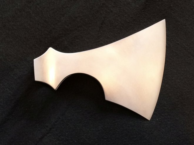
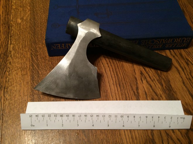
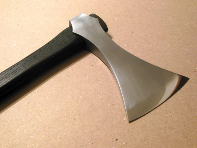
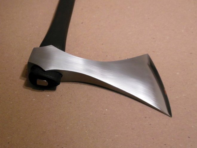
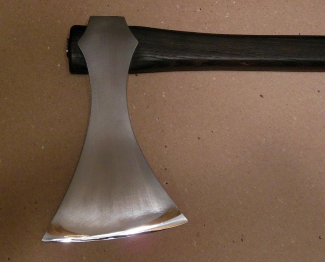
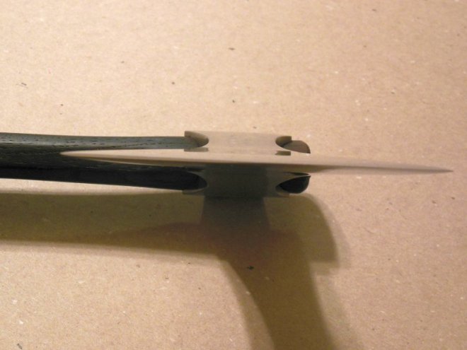
I’ve been able to create a variety of dies that serve different purposes.  Everything from drawing dies to beveling dies.  I even made a lateral drawing die that is on an angle for drawing axe blades out sideways.  This is quite helpful when make Type M axes.  I have a large set of flat dies I use for pattern weld billets.  The bottom die has holes drilled into it so I can insert a set of thickness stops.  Since even 25 tons is not capable of crushing cold steel, these stops allows me to precisely forge a hot billet to a desired thickness.  It comes in handy when I am making twist pattern and I want to make sure the billet it exactly drawn out to my target thickness.

Overall, I am quite happy with this press.  I was happy that I went with the bigger motor.  The press has very little lag or recovery time.  I pretty much have a massive amount of pressure available whenever I need it.  The ideas for different dies are limitless, so I can reduce my workload no matter what I am trying to forge.  If you have any question, I’ll do my best to help.  Just send me an email at ericmycue374@comcast.net.